To meet the requirements for extended operation of a marine titanium alloy stop check valve, this paper describes the structural characteristics of the redesigned extended-operation valve. Theoretical analysis indicates that the proposed design offers improved stem stability and operational reliability compared to the conventional approach of directly lengthening the valve stem. Additionally, the manufacturing processes for the extended valve bonnet and extended valve stem are examined, providing a technical reference for the structural design of extended-operation marine valves.
The titanium alloy stop check valve combines the functions of both shutoff and backflow prevention. Featuring excellent corrosion resistance, lightweight construction, and high reliability, it is widely used in shipboard seawater pipeline systems. When designing and installing ship piping systems, it is often necessary to extend the valve actuation mechanism, which may include handwheels, gearboxes, or electric actuators, to a safer and more accessible location that remains operable and is less likely to be submerged in seawater during emergency situations. Specifications clearly state that the handwheel or manual operating device for the main seabed valve on each side must be positioned at least 450 mm above the grating deck. The emergency water intake for the main engine should typically connect to the main cooling water pump and be fitted with a stop check valve. The valve stem must be suitably extended to ensure that the handwheel reaches 450 mm above the grating.
Currently, shipyards report that, for valves requiring extended operation, suppliers commonly extend the valve stem directly. However, this approach often presents risks such as poor sealing performance and difficulty in manual operation. In response to both operational requirements aboard vessels and customer feedback, this paper uses a specific product as a case study to explore the design and manufacturing of a reliable extended-operation titanium alloy stop check valve.
Nominal Diameter: DN125
Nominal Pressure: 2.5 MPa
Applicable Temperature: 0 to 36°C
Medium: Seawater
Material: Titanium and Titanium Alloy
Extended Operation Size: When the valve is in the closed state, the distance from the centerline of the flow channel to the top of the handwheel is 830 mm.
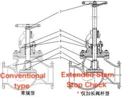
1. Valve body 2. Valve disc 3. Valve stem 4. Valve bonnet 5. Press sleeve 6. Press plate 7. Handwheel
Figure 1: Conventional Type and Extended Stem Stop Check Valve
As shown in Figure 1, both a conventional marine stop check valve and a stop check valve with a directly extended stem are illustrated. It can be observed that the extended stem stop check valve is essentially based on the conventional design, with the stem extended to meet the handwheel height requirement, while other structures remain unchanged. Currently, shipyards have reported that this type of stop check valve, with a directly extended stem, suffers from poor structural rigidity and low operational reliability. Over time, and with frequent operation, issues such as valve stem shaking and seal leakage are likely to occur.
To address the issues associated with the extended stem, an extended operation stop check valve with an extended stem and valve bonnet structure has been designed. The main components are based on the structure shown in Figure 1, with the addition of a guide sleeve (item number 8). The updated structure is illustrated in Figure 2.
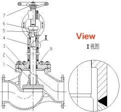
1. Valve body 2. Valve disc 3. Valve stem 4. Valve bonnet 5. Press sleeve 6. Press plate 7. Handwheel 8. Guide sleeve
Figure 2: Extended stem and valve bonnet type stop check valve
Inspired by the long-necked valve structure commonly used in low-temperature applications, the extended valve bonnet is welded from a flange, pipe, and bracket casting. The extended titanium alloy valve bonnet does not adopt an integral casting design. If cast as a hollow structure, the casting performance would be poor due to the long length and thin walls of the valve bonnet. Additionally, defects in the inner hole would be difficult to detect or repair. Alternatively, casting it as a solid structure would increase material costs. Furthermore, due to the extended length of the valve bonnet, the tool rod would need to be excessively long during the processing of the inner hole, leading to significant machining vibration, challenges in maintaining machining accuracy, and an overall increase in processing difficulty.
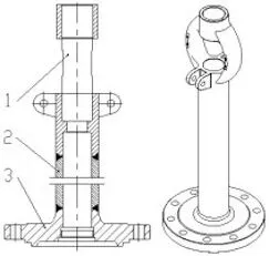
1. Bracket 2. Pipe 3. Flange
Figure 3 Extended bonnet structure
As shown in the partial enlarged view in Figure 2, after the valve stem is extended, the upper seal of the valve bonnet adopts an upward structure. This design prevents the valve bonnet cavity from forming a closed area, which enhances the sealing of the upper seal structure and allows for the online replacement of the packing. Additionally, the increase in the diameter of the section below the upper seal of the valve stem improves the rigidity of the extended valve stem.

1. Valve stem 2. Guide sleeve 3. Extended valve bonnet
Figure 4: Guide Sleeve Structure
As shown in Figure 4, the guide sleeve is installed at the bottom of the valve bonnet, effectively adding an intermediate support for the valve stem. By increasing the constraint, this design prevents the valve stem from bending or deforming, thereby improving its stability.
When the stop check valve is in the closed state, the valve stem is subjected to axial pressure. The valve stem structure of the extended operation stop check valve is slender, and its stability must be verified using principles of pressure rod stability. The stability of the valve stem is compared and analyzed for three structural configurations: the conventional structure, the extension of only the valve stem (Scheme 1), and the extension of both the valve stem and valve bonnet (Scheme 2).
The slenderness ratio λ is calculated using the following formula:

Where:
dF is the valve stem diameter (mm).
lF is the calculated length of the valve stem. For the rotary lift stem, this refers to the distance from the highest point of the valve stem nut thread to the lower end face of the valve stem (in millimeters).
l0 is the distance from the lower support to the middle support. For the rotary lift stem, this is the distance from the lower end face of the valve stem to the middle support point (mm),
μλ is the length coefficient, which depends on the support form. The value is determined by referencing the Fl0/lFratio.
The support structure for the conventional design and Scheme 2 features an intermediate support, with a hinge support at one end and angular and linear constraints at the other end. The structure is shown in Figure 5(a). The support form for Scheme 1 is shown in Figure 5(b), where the lFsegment has a free constraint at one end and a hinge support at the other end (μλ = 1); the lF2 segment follows the same support configuration as Figure 5(a). The valve stem length coefficients and flexibility values for the three structural forms are shown in Table 1.
Table 1. Valve Stem Length Coefficient (μλ) and Slenderness Ratio (λ)
|
Form |
Example (mm) |
10/mm |
cmm |
Conventional Structure |
Flexibility |
|
Conventional Structure |
277 |
146 |
0.439 |
32 |
15.2 |
|
Scheme 1 - Original Section |
482 |
/ |
1 |
32 |
60.3 |
|
Scheme 1 - 12 Section |
277 |
146 |
0.439 |
32 |
15.2 |
|
Scheme 2 |
705 |
574 |
0.593 |
37 |
45.2 |
(a) Conventional structure and support form for Scheme 2 (b) Support form for Scheme 1
Figure 5: Support structure
The maximum flexibilities for the conventional structure, Scheme 1, and Scheme 2 are calculated to be 15.2, 60.3, and 45.2, respectively. The calculated flexibility of the valve stem under the conventional structure is less than the design allowable value of 30, and stability verification is generally not required. It can be observed that the flexibility of the valve stem in Scheme 1 is greater than that in Scheme 2. The higher the flexibility, the poorer the stability of the valve stem. Therefore, the valve stems in Schemes 1 and 2 are further analyzed for stability.
Where:
λL = critical slenderness ratio, related to material properties
E = material elastic modulus, in MPa
σp = material proportional limit, in MPa
The physical properties of TA31 titanium alloy are listed in Table 2. Based on the calculations for the valve stem made from TA31, the critical slenderness ratio λL is determined to be 38.3.
Table 2: Physical Properties of TA31 Titanium Alloy
|
Property |
Value |
|
Tensile Strength (σ<sub>b</sub>) |
840 MPa |
|
Proportional Limit (σ<sub>p</sub>) |
740 MPa |
|
Elastic Modulus (E) |
110 GPa |
When the slenderness ratio (λ) is greater than or equal to the critical slenderness ratio (λ<sub>L</sub>), the valve stem is considered a high-flexibility (high-slenderness) compression member, and the Euler formula is used to evaluate its stability.
Where:
n<sub>w</sub> — Stability safety factor, taken as 2.5
[σ<sub>y</sub>]<sub>w2</sub> — Allowable stress for high-slenderness compression members (MPa)
σ<sub>y</sub> — Compressive stress on the valve stem (MPa)
F — Total axial force on the valve stem when the valve is closed (N)
For a PN25 DN125 titanium alloy stop check valve, the total axial force on the valve stem during closure is approximately 45,000 N. Substituting this value into Equation (3) yields the results shown in Table 3.
The calculations demonstrate that both extension designs meet the required valve stem stability criteria. However, Scheme 2, which involves extending both the valve stem and the valve bonnet, results in reduced compressive stress, significantly increased allowable stress, and a marked improvement in overall stem stability.
Table 3. Valve Stem Stability Check Results
|
Scheme |
Slenderness Ratio (λ) |
Compressive Stress σ<sub>y</sub> (MPa) |
Allowable Stress [σ]<sub>w</sub> (MPa) |
|
Scheme 1 |
60.3 |
56.0 |
119.4 |
|
Scheme 2 |
45.2 |
42.8 |
212.6 |
In general, when operating a small-sized valve by hand, the palm should be perpendicular to the axis of handwheel rotation. For large-sized valves, both hands should grip opposite sides of the handwheel and apply force evenly. However, the installation conditions of valves on ships are often complex, including angled and side-mounted configurations. Additionally, considering the operating conditions during emergencies or under harsh environments, it is typically difficult for personnel to maintain a balanced circumferential force when turning the handwheel. This often leads to the application of an eccentric force F on the outer edge of the handwheel. As illustrated in Figure 6, this eccentric force, when simplified along the axis of the valve stem, decomposes into a torque component FD/2 and a lateral force F. These combined forces cause the valve stem to experience both bending and torsional deformation.
In Scheme 1, where only the valve stem is extended, the structure above the valve bonnet forms a cantilever. Under the action of the eccentric force, the valve stem is subjected to a maximum bending moment FL at the stem nut, leading to additional bending stress at the nut-stem interface. This negatively impacts the reliability of the connection between the valve stem and the stem nut. The longer the cantilever, that is, the larger the L, the greater the resulting additional stress.
In contrast, Scheme 2, which extends both the valve stem and the valve bonnet, positions the valve stem nut closer to the handwheel. In this case, L approaches zero, and the bending moment caused by the eccentric force can be largely ignored. This structure is less affected by the valve’s installation orientation or by uneven handwheel operation, ensuring high operational reliability under varying conditions.
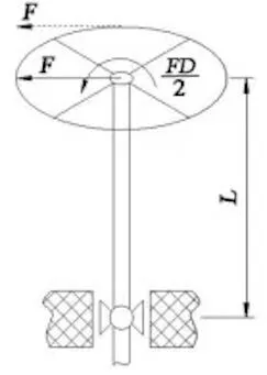
Figure 6 Handwheel subjected to eccentric force
The titanium alloy extended valve bonnet is manufactured through a combination of rough machining, welding, and finish machining. During the welding of the bracket, pipe, and flange, the weld positions must be arranged to avoid the upper sealing area. As indicated by dimensions d1 and h in Figure 7, in order to minimize deformation during welding, the joints between the pipe, bracket, and flange are designed with a “lock-bottom” structure. The pipe socket is inserted into both the bracket and the flange to ensure accurate assembly alignment and reduce the impact of welding deformation. A low-current welding method is used to control the interlayer temperature and the thickness of each weld bead. After every weld, the coaxiality of the inner holes at both ends of the extended valve bonnet must be measured and monitored. The processing steps for the valve bonnet are shown in Figure 8.
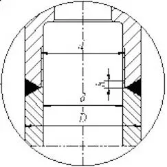
Figure 7: Welding Groove Diagram
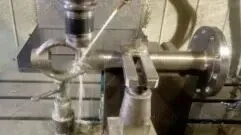
Figure 8: Valve Bonnet Processing
Compared with steel and aluminum, titanium alloy has significantly lower thermal conductivity. During cutting, heat does not dissipate quickly, causing high temperatures to accumulate in the cutting area. This can lead to issues such as reduced machining accuracy and tool wear or damage. Therefore, to ensure thermal stability during titanium alloy machining, careful consideration must be given to tool selection, feed rate, and cutting fluid.
The titanium alloy extended valve stem has a length of 788 mm and a diameter of 37 mm, giving it an aspect ratio of approximately 21. This slender geometry makes the stem prone to deformation during machining. To maintain the cylindricity and coaxiality of the valve stem, rough and semi-finish machining processes are introduced to gradually relieve machining stress. In addition, natural aging is applied before the final machining stage to fully release internal stress. These combined measures ensure the dimensional accuracy and structural integrity of the extended valve stem.
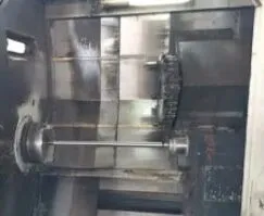
Figure 9: Valve Stem Processing
A design for an extended operation stop check valve has been developed, featuring a structure that simultaneously extends both the valve bonnet and valve stem. Theoretical analysis shows that, compared to a solution that only extends the valve stem, this design provides better valve stem stability and improved operational reliability. The research outlines the manufacturing process for the titanium alloy extended valve bonnet and valve stem. After assembly, the product is flexible to operate and has successfully passed various factory tests and real-world application assessments. Field service feedback has been positive.